Choosing a solar wiring method affects voltage, current, inverter performance, cable size, and safety. This guide explores the top 10 ways to wire solar panels in series vs parallel, using practical examples from rooftop and small off-grid systems. A series string raises voltage while keeping current similar. A parallel array raises current while maintaining nearly the same voltage. The difference becomes visible at the combiner box, inverter terminals, and cable runs.
PV design expert John Wiles often emphasized, “The National Electrical Code is a minimum safety standard, not a complete design manual.” That warning matters here. A wiring diagram may look simple on paper, yet one shaded panel can reduce a series string’s output. Parallel circuits can preserve production better, but they may require thicker conductors, fuses, and careful overcurrent protection. Small details matter.
Measure twice.
The right choice depends on panel ratings, inverter limits, shading, distance, and local installation requirements. A 100-foot cable run can expose voltage-drop problems that remain invisible on a short test bench. I have also seen beginners focus only on total watts, overlooking cold-weather voltage. That is an easy mistake. This article compares both methods with clear layouts, realistic trade-offs, and installation checks. It also examines mixed configurations, charge-controller limits, connector compatibility, and common design errors. No single method wins every project. Careful calculation does.
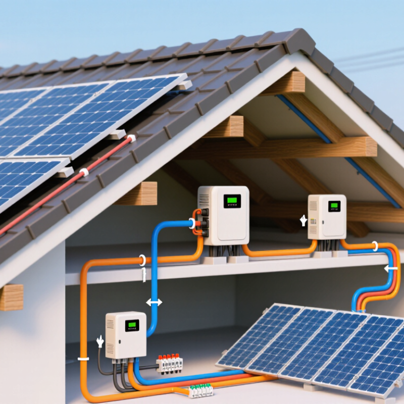
Solar panel wiring determines how much voltage and current reach the charge controller or inverter. In a series connection, panel voltages add while current stays close to one panel’s rating. This setup suits longer cable runs and controllers with higher voltage limits. However, one shaded panel can reduce the string’s output. I have seen this mistake during rooftop testing: a small chimney shadow affected the whole series string.
Parallel wiring keeps voltage similar to one panel but increases total current. It can perform better when partial shading affects only one branch. Yet thicker cables, branch fuses, and careful connector checks may be necessary. Hybrid connections combine series strings in parallel. They can balance system voltage and current, but every string should use matching panels with similar orientation and electrical ratings. A design may look efficient on paper and still perform poorly after installation.
Tips: Check the controller’s maximum input voltage before connecting panels. Calculate the cold-weather open-circuit voltage, not only the label value. Use a multimeter to confirm polarity. Keep cable lengths similar between parallel branches. Secure connectors against moisture, heat, and physical strain. Never connect panels casually while ignoring current ratings. An experienced installer should verify protection devices and grounding, because small wiring errors can create hot spots or unstable charging. Personally, I would recheck every connection after the first sunny day. Field conditions often reveal assumptions that calculations miss.
For accurate sizing, begin with each panel’s operating voltage and current. Six panels rated at 40 volts and 10 amps produce 240 volts and 10 amps in series. Power equals voltage multiplied by current, so the array provides 2,400 watts under rated conditions.
In parallel, the same six panels remain at 40 volts, while current rises to 60 amps. The calculated power remains 2,400 watts. Simple math.
However, cable losses increase with current, making conductor size and connection quality more important. Series wiring usually reduces current and voltage drop, but shading one panel can affect the string’s output. Parallel wiring can limit shading impact, although combiner protection becomes more important.
Actual production will not match the label. Temperature, dust, irradiance, and inverter limits change results. The IEA PVPS Task 13 report identifies median crystalline-silicon system degradation near 0.5% annually, so long-term estimates should include gradual losses.
A panel’s voltage also falls as cell temperature rises. This is easy to overlook. Check the cold-weather open-circuit voltage before selecting equipment. I have seen otherwise correct calculations fail because the designer used nominal voltage instead of operating voltage. That mistake deserves a second look. Use measured conditions, manufacturer tolerances, and local installation rules before finalizing a series or parallel layout.
Wiring solar panels in series increases system voltage while keeping current roughly unchanged. This setup can reduce cable losses and suit a higher-voltage charge controller. However, every panel should have compatible electrical ratings. Check the open-circuit voltage, operating voltage, and current before connecting anything.
Work in dry conditions and switch off the system’s disconnects. Covering the panels can reduce output, but sunlight may still create voltage. Inspect each cable and connector for cracks, looseness, or reversed polarity. Use a multimeter to identify the positive and negative leads. Connect the positive lead of one panel to the negative lead of the next panel. Continue this pattern across the string. Leave the first negative lead and final positive lead as the array output. Do not force mismatched connectors.
Measure the completed string before connecting it to a controller or inverter. The measured voltage should be close to the combined panel voltage, allowing for temperature and sunlight. In cold weather, voltage can rise significantly, so compare the calculated maximum with the controller’s limit. A shaded panel can reduce the performance of the entire series string. That detail is easy to underestimate. If readings look wrong, stop and trace each connection again. A qualified electrician should handle final system integration, grounding, and protection devices.
Wiring solar panels in parallel keeps the voltage close to one panel’s rating while increasing available current. Before connecting anything, read each panel’s voltage, current, and connector polarity. Never guess. Confirm the charge controller or inverter accepts the combined current and voltage.
Mount the panels securely, then place them in the same orientation whenever possible. Measure open-circuit voltage with a multimeter before making the final connection. Connect positive leads through a suitable combiner or fuse, and join the negative leads separately. Use cable sized for the expected current and cable length. Tighten terminals firmly, but do not crush them. A loose connection can create heat behind an apparently normal panel.
For a hybrid system, connect equal panels in series strings first. This raises voltage while keeping string current similar. Then connect matching strings in parallel to increase current. Each string should contain the same number of panels with similar electrical ratings. Check the controller’s maximum input voltage during the coldest expected weather, because panel voltage rises in low temperatures. I would also compare string voltages before connecting them together. Small differences may be acceptable, but large differences deserve investigation. This step is easy to skip. Do not mix shaded and unshaded panels casually; uneven sunlight can reduce output and complicate troubleshooting. Keep a wiring diagram near the equipment, and recheck polarity before energizing the system. A qualified electrician should inspect unfamiliar or high-voltage installations.
Choosing series or parallel wiring starts with safety, not maximum output. Series connections increase voltage while current stays similar. Parallel connections increase current while voltage remains similar. Before connecting anything, check the inverter’s operating range and maximum input voltage. Cold weather can raise panel voltage beyond the expected value. That detail is easy to miss.
A safe design considers ten practical points: panel ratings, temperature, shading, cable size, connector compatibility, fuse requirements, disconnects, grounding, battery limits, and inverter capacity. Series wiring often reduces cable losses, but one shaded panel can affect the string. Parallel wiring may perform better with uneven sunlight, yet it requires thicker conductors and careful overcurrent protection. Each string may need appropriate fusing. Never guess.
Inspect every connection for loose terminals, damaged insulation, or water entry. Keep cables supported, protected from sharp edges, and away from standing water. Experienced installers test polarity and voltage before energizing the system. They also follow local electrical rules and the equipment manufacturer’s instructions. A tidy layout is not automatically a safe one. I would still recheck the calculations after installation, especially when roof orientation or seasonal temperatures differ from the original plan. If the array is large or the wiring path is complex, have a qualified electrical professional verify it before use.
System voltage increases, while current stays roughly the same. This can reduce cable losses. Check every panel rating.
Connect one panel’s positive lead to the next panel’s negative lead. Leave the first negative and final positive leads as outputs.
Check open-circuit voltage, operating voltage, current, polarity, and connector compatibility. Inspect cables for cracks or looseness.
Panel voltage can rise significantly in cold conditions. Compare the calculated maximum voltage with the controller’s limit.
Yes. One shaded panel can reduce the performance of the entire string. This detail is easy to underestimate.
Series wiring raises voltage. Parallel wiring raises current. Parallel systems may handle uneven sunlight better but need thicker conductors.
Measure its voltage before connecting it to a controller or inverter. The reading should approach the combined panel voltage.
Work in dry conditions and switch off disconnects. Protect cables from sharp edges and standing water. Sunlight can still create voltage.
Have one verify grounding, protection devices, and final integration. Complex wiring deserves another calculation check. A tidy layout is not automatically safe.
This guide explains how to wire solar panels in series vs parallel and how each connection affects voltage, current, power, and system performance. Series wiring increases the total voltage while keeping the current similar to that of one panel, making it useful for reducing cable losses over longer distances. Parallel wiring increases current while maintaining a similar voltage, which can be suitable when a system requires greater current capacity. Hybrid connections combine both methods to achieve a balanced voltage and current output.
You will learn how to calculate expected electrical values, connect panels step by step, and identify important safety considerations before installation. The guide also compares the advantages and limitations of series, parallel, and hybrid configurations, including how shading, cable size, system voltage limits, protective devices, and equipment compatibility can influence your choice. By following these principles, you can select a safer and more efficient wiring method for your solar power system.
